Search This Blog

Showing posts with label COMSOL. Show all posts

Transformation & conversions are other tools that help us to modify our structures. These tools have lessened our complexity in building...


Transformation & conversions are other tools that help us to modify our structures. These tools have lessened our complexity in building geometry. Let us get to know about these operations.

Transformation:
These operations are useful when we need to modify our actual structure. Unlike Boolean or Partitions, we can't merge or split the geometry. 

Array: We can create a rectangular or linear array of the selected geometry by using array transformation. Rectangular array transformation will result in a rectangle while the linear one will extend along with the diagonal. Now you may ask, what will be the range of the array? The extensions are according to the equations below;

 extension (x/y direction) = size (x/y) * displacement (x/y)

Copy: We can copy the selected object and place it on the given coordinates in the displacement box. 
Mirror: This will mirror the object. It requires a point that lies on the point of reflection. Now if we want to draw a line based on a point, numerous straight lines or planes can be formed. So in which direction the object will be mirrored? That's why we need to provide a vector that is normal to the reflection plane/line. Now a few things to be noted;

Increasing X

Y fixed

Reflects to the right

Increasing Y

X fixed

Reflects upwards

Decreasing X

Y fixed

Reflects to the left

Decreasing Y

X fixed

Reflects downwards


Move: We can move the selected object to our desired position. We just need to specify the coordinates.
Rotate: The selected object can be rotated by giving the angle of rotation and the center of rotation. Centre of rotation is the point which will act as the reference while rotation.
Scale: We can increase or decrease the size of the object by giving the scale factor. Scale factor is the ratio to which the size will be updated. The scaling will be conducted taking the center of scaling as the reference. Isotropic scaling will give the same factor for both axes. But anisotropic scaling will give different factors for different axes.

Conversion:
◉ Convert to Solid
◉ Convert to Curve
◉ Convert to Point
◉ Split


◉ Chamfer: Chamfer calls for some vertices and a distance from the vertices. What actually it does, it goes along with every edge associated with the vertice. From the vertice, it calculates the specified distance along with every edge and put points. After that, the points are connected and the rest are discarded from the geometry.
◉ Fillet: It makes the vertices rounded according to the specified radius. Just assume that a rectangle can be transformed into a circle using fillet.


For better visualization, check out the tutorial video here: Transformation & Conversion


Building geometry or structures is very important in COMSOL as the simulation entirely depends on the structure. But there are only a few op...


Building geometry or structures is very important in COMSOL as the simulation entirely depends on the structure. But there are only a few options like circle, square, rectangle, polygon, etc. that COMSOL provides. What to do if our structure is something more than the basic blocks? Here comes the Boolean and Partition operations to modify the structures.

** We will be using 2D models and only the functions will be described. For better understanding please watch the video at the end of the article** 


What is Boolean?
Most of us may know about boolean algebra. It has only two variables; True/False, 0/1, Yes/No, etc. We can apply the same operations in case of structures. But eventually, you will find that, instead of Boolean, they more relate to Set operations. In COMSOL, the operations are named as;

 Union: This operation is like 'addition' process. We can turn multiple different domains into a single one using a union. Here, if we wish, we can leave the intersected boundary edges as it was or we can remove the edges.
◉ Intersection: We can keep the intercepted area of the domains by this operation.
◉ Difference: It is the 'subtraction' operation. It gives two selection window. One is for the domains to be added and the other is for the subtracted domains. The subtracted domains along with the intercepted portions with the added domains will disappear from the structure.
◉ Composition: Now composition allows us to make customized geometry. We just need to select the domains and make an equation, a boolean equation, that serves our purpose. 


Partition:
Partition basically tends to make parts inside the domains or objects. Now parts can be created inside the object body or on the edges.

Object Body: To make the parts inside the body, we either need another object to specify the part or some lines to separate the parts. To create parts with the help of another object, we need to go for the 'partitions objects' option and select the object to partition and the tool object.
Again if we want to partition the domains, we need to choose some vertices that will draw some lines and will create the partitions. For this, we need to choose the 'partition domains' and select the necessary parameters.
Edge Partition: This will part the selected edges according to the given ration. We just need to choose the edges here and fix the ration. This will create two separate partitioned edges from a single one.

Check out the video below to have better visualization: Boolean operations & Partitions


Image Source:
* COMSOL Multiphysics
* Stack Overflow


Till now we've discussed the pre-requisites to build structures in COMSOL. Today we will explore some of the base structures like circle...


Till now we've discussed the pre-requisites to build structures in COMSOL. Today we will explore some of the base structures like circle, rectangle, square, polygon, etc. This will lead us to build complex models in the future. 

Geometry Console:
Right-click on the geometry node and you will find 10 structures as;
* Circle
* Ellipse
* Rectangle
* Square
* Polygon
* Point
* Parametric Curve
* Line Segment
* Interpolation Curve
* Bezier Polygon

To build the specific structure, you just need to select the structure and the related settings will be available in the Settings window.

Geometry Settings:
No matter what geometry you choose, there'll be mostly similar segments in the settings window.


The flowchart briefly explains the functions of the geometry settings. But for some structures, there are some more options available. Let us talk about them separately.

Special Fields:
Sector Angle (Circle): One can modify the share of the circle by inserting the angle value here. For example, 360° for a full circle, 180° for half circle, 90° for quarter circle, etc.
Coordinates (Polygon): Takes the coordinates of the polygon.


Expression (Parametric Curve): As the name suggests, parameter refers to another variable (let 's') rather than actual variables (let x,y) in a problem. And the actual variables are expressed through that parameter by some equations. Therefore 's' requires a minimum and maximum value and the expressions for the actual variable. For example,

x= 0.5*s+2*s^2  and
y= 5*s-3*s^2 where  -1≤ s ≤1


Start & End Point (Line Segment): It calls for the selection of the start and endpoint of the line. One can manually enter the coordinates of the line by choosing coordinates in the specify dialogue box.
Data Source (Interpolation Curve): Similarly like the coordinates in Polygon, the same options are provided here for data entry (Vector, File, Table). One just needs to specify the data here.


Don't forget to watch the video on building project in COMSOL: Geometry in COMSOL Multiphysics


So, we're talking about the steps to form a design in COMSOL. And after a hazy discussion, we were left with 2 subnodes;  Component  ...


So, we're talking about the steps to form a design in COMSOL. And after a hazy discussion, we were left with 2 subnodes; Component & Study in the Model Tree. The immense significance of these 2 nodes calls for a separate discussion. Don't you think so? Let's first talk about the Study!

According to our early discussion, we know that the Study sets up the solver type (i.e. Stationary, Time-dependent, Frequency-dependent, etc.).


Model Wizard automatically creates the nodes under Study while simulation. Additional studies can be added from the study tab from the Ribbon.


So, we can switch between different studies and compute. Each study has a Compute button to run simulation for the selected study. The settings & boundary mode operations and configurations can be set here. It is very much important to simulate the model with the correct study. The result nodes will be added as per the selected study.

Coming to the Components node, it comprises of multiple sections as;

 Definitions: Defines the variables, boundaries, system selections, and their modifications.
✦ View: It gives the axes settings.
✦ Geometry: Gives the necessary options to build the model.
✦ Materials: Materials property like refractive index and others can be specified here. You can also add material in this node.
✦ Mesh: The whole model is divided into numerous small nonoverlapping elements. The behavior model is approximated by assembling all the elements' behavior. As COMSOL is based on the Finite Element Method (FEM), it is highly dependent on meshing. Here we can select the mesh type (rectangular, triangular, square, etc.), their size, and the relative setups.
✦ Physics: Gives selection options based on the selected Physics.
✦ Variables: Numbers, parameters, built-in constants, unary and binary operators can be set as Global or Local variable. Variables are listed under the Definition tab. Too many variables can be grouped together using the Node Group feature.


In the next segment, we will try to design a model. Till then explore & learn. Keep in mind, software can't be taught by articles. These articles are to provide a guide. One has to learn the software by exploring it.

And be with us for the next article and yes don't forget to check out the tutorial video: A simple Model in COMSOL Multiphysics on youtube.


Image Source:
* COMSOL Multiphysics


In the previous articles, we've discussed different features and UI of COMSOL. There's a lot yet to be discussed but it is a better ...


In the previous articles, we've discussed different features and UI of COMSOL. There's a lot yet to be discussed but it is a better idea to learn them through designing a structure. What do you think? But before jumping directly into the process, we first need to know which phases we need to follow.


Now have you ever tried to design a structure? Maybe no. But those who have tried to learn SOLIDWORKS or similar software, you may know the fundamental blocks are;

1) Designing blocks:
▣ Selecting the Material
▣ Specifying the Parameters 
▣ Selecting the Components

2) Simulation blocks:
▣ Defining the Mesh
▣ Selecting the Solver Type
▣ Creating the Simulation profile
▣ Defining the Boundary Conditions

From the previous article, we know that the necessary information regarding a model is concerned with the Model Builder Window (Model Tree). Let us explore this section a bit more deeply.


** We will be using Electromagnetic Waves, Beam Envelope > Boundary Mode Analysis as Physics & Stationary as Study. **


Model Tree

This is the resulting Model Builder Window. Here we can see a Root Node which is initially, set as Untitled.mph. This is named under the model file. Two subnodes, Global Definitions & Results are the basic ones. Under Globar Definition, we have the subnode of Material, which represents the material of the model. We can set up the material from the material library. Also, we can have the parameters here.

Parameters


Again the materials of the design can be selected from the Material Library. This library offers a vast option to choose the proper material even it offers user-defined materials!!!


Material Library


And under the Result subnode, we have,

1

Datasets

List of solutions

2

Derived Values

Defines values to be derived from the solution using post-processing tools

3

Tables

Stores the real-time simulation solution

4

Export

Defines numerical data, images & animations to be exported to files

5

Reports

Contains automatically generated reports about the model in HTML/MSW 


Results (Datasets)


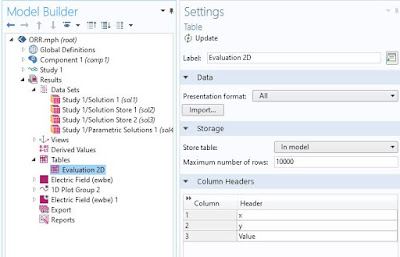
Results (Table)


As we can see there are additional subnodes in the result node which are not mentioned in the table, i.e. Views, 1D Plot Group 2, etc. These results are added during the simulation process. 
The reminder is that you can always edit the associated settings of each component of the model tree in the Settings Window.


Visit the next article COMSOL Multiphysics Part - 04: What It Takes To Design A Structure - II for Component & Study discussion.


Image Source:
* Freelancer


** Using COMSOL Multiphysics  5.3  in Windows  10 First of all, we want to click on the software icon and after doing that we are given two ...


** Using COMSOL Multiphysics 5.3 in Windows 10


First of all, we want to click on the software icon and after doing that we are given two options as;

* Model Wizard: As we've said earlier, COMSOL provides us with various options to set the environment. adding multiple physics and study and the nature of the simulation. By choosing the model wizard we will get the options to set the environment as per our project requirements. The model wizard gives the following setups

01. Space Dimension (3D,2D Axisymmetric, 2D, 1D, 1D Axisymmetric, 0D)
02. Physics 
03. Study
 
* Blank Model: Here we don't get any option to set the environment for the object. The blank model directly takes us to the design window. We can set the requirements later on.


Now, we'll continue with the Model wizard. After choosing the model wizard, we need to specify the space dimension, Physics, and the specific study. Space dimension specifies the dimension of the model, Physics specify the physics interfaces that are applied to the model i.e. Acoustics, Heat transfer, AC/DC, Electrochemistry, Heat flow, etc. After choosing interface(s), the description of the associated interface is shown in the window. And the Study specifies the type of solvers used for the computation i.e. Stationary, Time-dependent, etc.


After setting up the environment and solver type, we will be forwarded to the designing window. One thing to notice here that, the recommended options of the Physics and Study are based on the previous selection. That means the available options for Study will depend on the selection of the kind of Physics. And in the designing window, the available options will depend on the selection of the environment and the solver.

COMSOL Desktop:
Now in the design window, there are 6 different segments;
 
▶ Quick Access Toolbar: It contains the quick buttons for different functions like open/close file, undo/redo, copy/paste, delete. The contents here can be accessed through Customize Quick Access Toolbar.


▶ Ribbon: This tab contains the buttons and dropdown menus to control the modeling process. Home, Definitions, Geometry, Materials, Materials, Physics, Mesh, Study, Results, Developer buttons are available here.


▶ Model Builder Toolbar: The model builder toolbar comprises of model tree. It is linked with the Ribbon tabs. It gives an overview of the model. All the functionalities and operations are controlled via this toolbar. It also suggests the next step for model building. The results and solving processes are linked here.


▶ Settings Window: Settings window contains the setting options to set the parameters and select options of the model. The settings are related to the selection of the node in the model builder tab.


▶ Graphics Window Toolbar: The designing of the model appears here. It offers interactive graphics for the Geometry, Mesh & Results nodes. The Graphics window has the operations to rotate, zoom, select, pan, and many more.


▶ Information Windows: This window holds the Messages/Progress/Log/Table information throughout the modeling and simulation process.


We need to know the difference between the kind of contents they represent to act as per them. It goes like this, 

01

Messages

Information about the current session

02

Log

Information from the solver

03

Progress

Progress information about the solver

04

Table

Numerical data in table format


So it may be a pretty enough introduction to the interface. Wait for the next part..... COMSOL Multiphysics Part: 03: What It Takes To  Design A Structure-I


Visit the tutorial video on COMSOL Multiphysics: User Interface of COMSOL Multiphysics on youtube.


              Here comes another simulation software! For EEE students, Proteus, MATLAB, PSpice, PSIM, etc. are the most familiar simulation...


Here comes another simulation software! For EEE students, Proteus, MATLAB, PSpice, PSIM, etc. are the most familiar simulation software. ''An uncommon software with a messy user interface!''- this may be the most probable reaction of a beginner at first glance. But this can be a useful tool for a researcher indeed.

What does it do?
COMSOL is mainly a design and simulation software. The specialty of this software is, it can create multiple physics interface. There are plenty of ''Physics'' options to create the environment to figure out the test object's behavior in those physical environments.

What does it provide?
As it is said earlier, COMSOL provides a variety of options to customize the user's project up to the desired scale.

▶ It can provide physics interface of Electrical, Mechanical, Chemical, Fluid, Acoustic, Electromagnetic, Plasmonics, Photonics, Multipurpose & Interfacing, etc. 
▶ It can provide different studies like static, continuous, etc. 
▶ It provides diversified facilities to design the object according to the project specifications.
▶ The equations are predefined in the software for each physic. The simulation is done based on the equations.
▶ Multiple options to import object structure or design from CAD, Solidworks, or MATLAB. It offers live links.
▶ COMSOL provides a very user-friendly and interactive algorithm that points out the errors made by the user and gives suggestions to correct the errors.
▶ Runs finite element analysis and solver for multiphysics simulation software.
▶ And many more.............

COMSOL team describes their key features as;

⦿ Optimizing and verifying real-world devices and processes with simulation.
⦿ Multiphysics modeling provides accurate results.
⦿ Follow a consistent model workflow.
⦿ Geometry modeling & interfacing with CAD software.
⦿ Predefined interfaces and features for physics-based modeling.
⦿ Transparency and flexibility via equation-based modeling.
⦿ Automated and manual meshing.
⦿ Study step sequence, parameter studies, and optimization.
⦿ Step-of-the-art numerical methods for accurate solutions.
⦿ Extended visualization and post-processing tools for publication-ready modeling results.
⦿ Close the gaps between analysis, design, and production by building simulation applications.


This seems a horrible illustration for the introduction but we hope to explore all the above-mentioned features in the next parts.
Visit our next article on the user interface of COMSOL;  COMSOL Multiphysics Part - 02: User Interface (UI)


Visit the tutorial video on COMSOL Multiphysics: Introduction to COMSOL Multiphysics on YouTube.