Search This Blog

Showing posts with label Projects. Show all posts

Here we have a sensor module to measure the temperature and humidity of the environment. Don't get so excited. If you want to try it to ...


Here we have a sensor module to measure the temperature and humidity of the environment. Don't get so excited. If you want to try it to make your thermometer to measure body temperature, you need to shake your brain a little bit. This 2 in 1 sensor module serves our purposes in environmental projects at a cheap price where temperature & humidity can be used as a trigger. Unlike most other sensors, this gives a digital output.

In & Out:
We can have only the sensor part or the sensor module pack. Whatever may it be, apparently, we can see, a cage-like structure, 4 output pins, and in the sensor module, we can see some resistors, capacitors along with an IC. The cage is to protect the sensor circuitry.

Sensors


As you can see two sensors, build the entire module; 1. The Humidity Sensor & 2. Temperature sensor (Thermistor).
This module has the simplest construction, one sensor can have. Before jumping into the working principle, let us have a basic idea of the sensors.

Humidity Sensor: The construction of the humidity sensor includes a moisture-holding substrate that changes its conductivity with the change of the environment. The substrate is placed between two electrodes. The substrate absorbs the water vapor and releases ions. Consequently, the conductance increases which is proportional to the relative humidity. The change in resistance between the electrodes is sensed & processed by the IC and creates the output.

Construction of humidity sensor

Now it leaves no place of questioning, why it's called the capacitive type humidity sensor. This capacitive nature provides accurate measurements regarding humidity. (Dew point, Relative Humidity, Absolute Humidity, etc.)

Temperature Sensor: This is nothing but a thermistor that changes its resistance with the change in temperature. It has a negative temperature coefficient (NTC) which means its resistance decreases with the increment of temperature. 
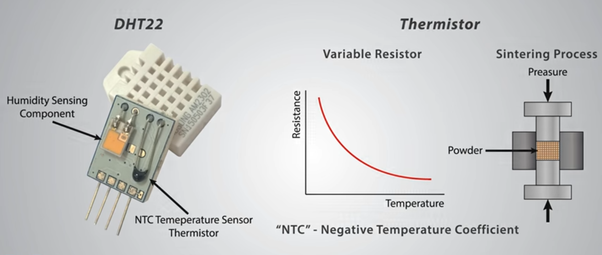


Sintering refers to the inclusion of semiconductor materials to provide a larger change in resistance with just small changes in temperature.

Pinouts:
The sensor has 4 output pins; Vcc, Data, NC, GND respectively.

Working Principles:
Firstly connect the sensor as per the following diagram and don't forget to add the pullup resistor. (Not required for the sensor module as it has an inbuilt pullup resistor mounted on the PCB)

DHTXX has 8 bit MCU, therefore, it sends data in 8-bit sequences. After sending the starting pulse by the host MCU, DHTXX starts sending data. Both the humidity & temperature data are sent through the data pin in serial transmission line.


Data(40 Bit)= Integer byte of RH; Decimal byte of RH; Integer byte of temperature; Decimal byte of temperature; Checksum/Parity byte

The successful transmission of data is checked by the parity byte. In case of failure, again the data is transmitted.

Parity(8 Bit)= Integer byte of RH +Decimal byte of RH +Integer byte of temperature +Decimal byte of temperature

An example be like,
Data:       00110101  00000000  00011000  00000000  01001101
Parity:     00110101+00000000+00011000+00000000 = 01001101
Decision: Data matched!
Humidity: 00110101 = 35H = 53% RH
Temperature: 00011000 = 18H = 24°C

Accuracy & Specifications:
✦ Temperature Range: 0-50°C with ±2% accuracy
✦ Humidity Range: 20-80% with ±5% accuracy
✦ 3.3 ~5V MCU system.
✦ Operating Current: 0.3~5.5 mA
✦ 16-bit resolution
✦ Long term stability
✦ DHT22 has a more precise, accurate & wider range of working.
✦ 1 Hz sampling rate.


Pitfalls:
This sensor can only provide data that are up to 2 seconds old.

Application Area:
✦ Humidity & temperature measurement
✦ Local weather station
✦ Automatic climate control sensor
✦ Environment monitoring device

Other Sensors:
AM2302, SHT71, TMP100, DS18B20, etc.


Reference Articles:

Image Sources:
* DHgate.com
* Technobyte
* The Engineering Projects
* How to Mechatronics
* Simple-Circuit.com
* ElectronicsHub
* How to Mechatronics


Previously we're talking about Ultrasound Sonar Sensor ( HC-SR04 ) that could detect the presence of an obstacle and could measure the d...


Previously we're talking about Ultrasound Sonar Sensor (HC-SR04) that could detect the presence of an obstacle and could measure the distance also. Compared to the well-known 'Bug-eye' sensor HC-SR04, we've got another less familiar sensor form Maxbotix, namely Ultrasonic Range Finder-LV-Maxsonar-EZ series; EZ0, EZ1, EZ2, EZ3, EZ4.
Maybe you're taking it just as another product from a different manufacturer but does that really satisfy your curious mind? Don't you want to know what's different in it? Spare some of your time and quench your thirst.


What's Inside?
The basic working principle of this one is the same as HC-SR04 but the input and output controls are different and as you can see there is only one transducer while HC-SR04 had 2 of them. Moreover, it has 7 pins.


Pin No.

Pin Name

Description

1

BW

This should be kept low or open for serial output on Tx. If kept high, Tx will send pulse instead of serial data

2

PW

Pulse width representation of the range

3

AN

Analog output voltage with a scaling factor of Vcc/512 per inch 

4

RX

Internally pulled high. The sensor will stop ranging if Rx is held low 

5

TX

Delivers asynchronous serial with RS232 format

6

Vcc

2.5V~5.5V input power

7

GND

Ground


What's different?
This one is a little bit costly (~30$). But this module provides better facilities.

Short to long-range Detection: Detects objects from 0-254 inches (6.45m)
Sonar Range Information: From 6-254 inches with 1-inches resolution. Objects from 0-inches to 6-inches typically range as 6 inches
Operating Frequency: 42KHz
Quality Beam Characteristics: EZ0 holds the maximum sensitivity and wide beam pattern among the EZX series. The beam gets narrower in the subsequent models. Check datasheet for the beam patterns.
3 Different Outputs: The sensor provides continuously updated Analogue, Pulse Width & RS232 serial data when it is allowed to operate in the default mode of operation (free-run).
Multiple Sensor Chain: One can use multiple sensors in a single system. The outstanding feature is that MaxSonar provides a way to avoid cross-talk and interference. There are 3 ways to make the chaining.

    AN output constant loop: The sensors will be triggered sequentially for ranging.


    AN output commanded loop: The sensors are triggered sequentially and the last one again triggers the first one thus creating an infinite loop.


    AN output simultaneous operation: All the sensors are triggered at the same time.


Working Principle:
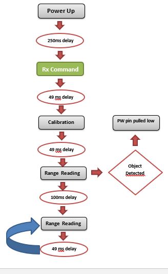
The operating principle of this sensor is pretty simple. One just needs to send the trigger through the Rx pin. The sensor runs on a cycle of 49ms.


Image Source:
* TechBazar
* MaxBotix
* ece.ucsb.edu


As we talked earlier, we have different kinds of Arduino boards with different specifications. These boards extend the area of working with ...


As we talked earlier, we have different kinds of Arduino boards with different specifications. These boards extend the area of working with Arduino. For different purposes, different boards are preferred over others and more compatible. We now want to talk about them. In this part, we'll be demonstrating;

-- Arduino Uno
-- Arduino Mega
-- Arduino Due
-- LilyPad Arduino
-- Arduino Leonardo
-- Arduino Nano
-- Arduino Micro

But before that, we need to have some ideas on some terms;

⌕ Flash Memory: It is the program memory of the Arduino where the Arduino sketch is stored.
⌕ SRAM: It stands for Static Random Access Memory. The sketch creates and manipulates variables here when the programs run.
⌕ EEPROM: It is the memory where the programmers store their long-term information.

Now the fact to notice is that Flash memory & EEPROM are non-volatile memories that persist for a long time after the power being off. But the SRAM data is lost when the power is cycled.


▶ Arduino Uno R3 (Revolution 3): 
Arduino Uno is the best tool for small projects. It provides a moderate number of input & output pins with compatible specifications. It uses the ATmega 328P onboard chip.


1

Microcontroller

ATmega328P

2

Operating Voltage

5V

3

Input Voltage
(recommended)

7-12V

4

Input Voltage
(Limit)

6-20V

5

Digital I/O Pins

14

6

PWM Pins

6

7

Analog Input Pins

6

8

DC Current per
I/O Pin

20mA

9

DC Current for
3.3V Pin

50mA

10

Flash Memory

32 KB

11

SRAM

2 KB

12

EEPROM

1 KB

13

Clock Speed

16 MHz

14

LED Built-in Pin

13


0.5 KB of the Flash Memory is used by the bootloader. We'll get to know more about this board later on. 

▶ Arduino Mega: 
Mega is called the 'Big Brother' of Uno! Mega offers more input & output pins than Uno and also larger memory components. Usually, Mega is preferred for large projects where many components are needed to be connected with Arduino that Uno can't supply.


1

Microcontroller

ATmega2560

2

Operating Voltage

5V

3

Input Voltage
(recommended)

7-12V

4

Input Voltage
(Limit)

6-20V

5

Digital I/O Pins

54

6

PWM Pins

15

7

Analog Input Pins

16

8

DC Current per
I/O Pin

20mA

9

DC Current for
3.3V Pin

50mA

10

Flash Memory

256 KB

11

SRAM

8 KB

12

EEPROM

4 KB

13

Clock Speed

16 MHz


8 KB of the Flash Memory is used by the bootloader. Get to know more by clicking here.

▶ Arduino Due:
Due resembles to Mega in appearance but along with memory upgradations, Due is the first Arduino with 32 bit ARM core microcontroller. Thus Due is able to provide more power to larger projects. But a major fact to notice, it supports 3.3 V input voltage.


1

Microcontroller

AT91SAM3X8E

2

Operating Voltage

3.3V

3

Input Voltage
(recommended)

7-12V

4

Input Voltage
(Limit)

6-16V

5

Digital I/O Pins

54

6

PWM Pins

12

7

Analog Input Pins

12

8

Analog Output Pins

2 (DAC)

9

DC Current for
5V/3.3V Pin

800mA

10

Flash Memory

512 KB

11

SRAM

96 KB (two banks: 64 KB & 32 KB

12

EEPROM

4 KB

13

Clock Speed

84 MHz

14

Total DC Output Current on
all I/O lines

130 mA


Get to know more by clicking here.

▶ Arduino Leonardo:
Leonardo is the first development board of Arduino. It differs from other boards to has a built-in USB communication that doesn't require a secondary processor. Another thing is that the libraries allow the board to act as a keyboard or mouse while connecting to a computer!


1

Microcontroller

ATmega 32u4

2

Operating Voltage

5V

3

Input Voltage
(recommended)

7-12V

4

Input Voltage
(Limit)

6-20V

5

Digital I/O Pins

20

6

PWM Pins

12

7

Analog Input Pins

12

8

DC Current per I/O pin

40 mA

9

DC Current for
3.3V Pin

50 mA

10

Flash Memory

32 KB (4KB used by bootloader)

11

SRAM

2.5KB

12

EEPROM

1 KB

13

Clock Speed

16 MHz


Get to know more by clicking here.

▶ LilyPad Arduino: 
This is the most good looking and tiny sized Arduino board. This board is specially modified for e-textile. The purpose of this one is to use wearable clothes. Along with I/O pins, there are board sensors, specially built for e-textiles. The board provides large pin-out holes that made it easy to sew and connect through conductive threads. And will you believe if I say this Arduino is washable !!!


1

Microcontroller

ATmega 168

2

Operating Voltage

2.7-5.5 V

3

Input Voltage
(recommended)

2.7-5.5 V

4

Input Voltage
(Limit)

-

5

Digital I/O Pins

14

6

PWM Pins

6

7

Analog Input Pins

6

8

DC Current per I/O pin

40 mA

9

DC Current for
3.3V Pin

 -

10

Flash Memory

16 KB (2KB used by bootloader)

11

SRAM

1 KB

12

EEPROM

512  KB

13

Clock Speed

8 MHz


Therefore, this Arduino is useful for wearable projects like Gesture Controlled Robot. Get to know more by clicking here.

▶ Arduino Nano:
Nano is the smallest member of the Arduino family to make projects with. The main feature of it is, it is breadboard friendly, light with mostly resembles the functionalities of  Dueemilanove. It lacks the power jack. A mini- B USB cable is used instead of the standard ones.


1

Microcontroller

ATmega 328

2

Operating Voltage

5 V

3

Input Voltage
(recommended)

7-12 V

4

Input Voltage
(Limit)

-

5

Digital I/O Pins

22

6

PWM Pins

6

7

Analog Input Pins

6

8

DC Current per I/O pin

-

9

DC Current for
3.3V Pin

-

10

Flash Memory

32 KB (2 KB used by bootloader)

11

SRAM

2 KB

12

EEPROM

1 KB

13

Clock Speed

16 MHz


Get to know more by clicking here.

▶ Arduino Micro:
The Micro has an appearance just like Nano but if we talk about features, it can be said as a mini version of Arduino Leonardo with the additional feature of breadboard friendly. Using ATmega 32U4 like the Leonardo, it allows the Micro to appear as a mouse or keyboard to a connected computer in addition to a virtual (CDC) serial/ COM port.


1

Microcontroller

ATmega 32U4

2

Operating Voltage

5 V

3

Input Voltage
(recommended)

7-12 V

4

Input Voltage
(Limit)

6-20

5

Digital I/O Pins

20

6

PWM Pins

7

7

Analog Input Pins

12

8

DC Current per I/O pin

20 mA

9

DC Current for
3.3V Pin

50 mA

10

Flash Memory

32 KB (4 KB used by bootloader)

11

SRAM

2.5 KB

12

EEPROM

1 KB

13

Clock Speed

16 MHz

Get to know more by clicking here.


Check out the next article to know about the other members of Arduino in Arduino Family: Part-02


Reference Articles:


Image sources:
* EIProcus
* circuito.io
* classes.engineering.wsutl.edu
* Wiring Library
* Arduino for Projects
* Pininterest
* ChillRain
* Flickr