Search This Blog

Hats off to the single-board microcontrollers that created a wind of inspiration among the youngsters in Bangladesh. It was not so long ago ...


Hats off to the single-board microcontrollers that created a wind of inspiration among the youngsters in Bangladesh. It was not so long ago when the tech-enthusiasts had to wander a lot to enhance their skills regarding robotics and related stuff. Arduino, the most basic & simple MCU gave them a chance to create, innovate & critical thinking!

Students ranging from school to university have wide usage in Arduino in daily projects, assignments, or contests. There's no room for thinking that, these MCUs are limited to "Fun Projects" only. Security systems, installations, safety devices, and many more applications, for example, CNC machine, 3D printer, Writing machines, Drones, Quadcopters have Arduino based construction. Projects related to the social or environmental crisis (i.e. Automatic hand washing machine during COVID-19, Gas emission measurement devices, etc.) add much more importance to it.


The inventors of these MCUs could be mean by confining their efforts to Arduino only but they didn't choose to and as a result, we were gifted with Raspberry Pi, the giant of robotics & system coding! What's not possible to do with Raspberry Pi! Where Arduino puts a limitation for the great thinkers to implement their imagination practically, Raspberry Pi offers the window to imagine beyond the boundary. A silly example may be given in this context, to create an interactive display system Arduino demands complex blocks of coding and a heavy list of components where Raspberry Pi has an inbuilt display port and necessary settings!


Arduino, Raspberry Pi are merely two examples of single-board microcontrollers. The tech world is giving more and more advanced versions. Many manufacturers have different products like NodeMCU, Orage Pi, and many more. But the question stands here, "How much of it we're getting?" 


In Bangladesh, we have a mere chance or access to these tech-giants. In many engineering universities, students are offered some courses that give the introduction and the rest are upon personal interest of students. This rarely helps to build a strong network of innovators to serve the country or to pass the inspiration to the youngers. It goes without saying that, these embedded systems require comprehensive knowledge of coding & designing sense. But there's always a starting point and unfortunately, we have delayed the point too far.


Students, from their early ages, should be given space to go for these things. We lack the opportunities to learn from the experts! Yes, there are some entrepreneurs or organizations that try to convey the goal and motivation but they are not too many. 


The chain of motivation could be hard to realize if it was a couple of years ago but in today's era, every student has access to the internet with their own smart devices. Ironically this accessibility is used for scrolling Facebook pages or for online gaming.


≢ Why don't we inspire our nearby students to build their own game rather than getting stuck to meaningless games? Have you ever said to your child that it is possible to build a game using Arduino?


≢  Have you ever thought of building a website using Python/Django?


≢  Have you ever thought of making an android app? 


≢  Or have you ever said to your younger brother that he can build his own operating system or pocket laptop using Raspberry Pi?


If not, then how can we expect to grow our own community of skilled people or to develop an embedded system in our country? Think about it!


Image Source:

* Medium
* Project Showcasing; Esonance, IUT
* Meccanismo Complesso
* VectorStock


Here we have a sensor module to measure the temperature and humidity of the environment. Don't get so excited. If you want to try it to ...


Here we have a sensor module to measure the temperature and humidity of the environment. Don't get so excited. If you want to try it to make your thermometer to measure body temperature, you need to shake your brain a little bit. This 2 in 1 sensor module serves our purposes in environmental projects at a cheap price where temperature & humidity can be used as a trigger. Unlike most other sensors, this gives a digital output.

In & Out:
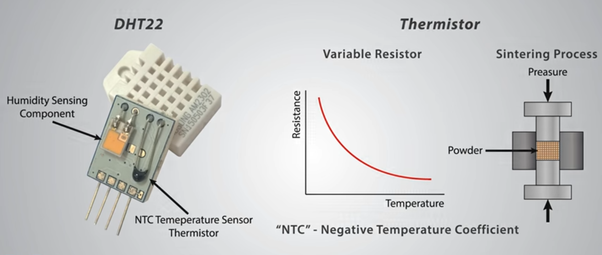
We can have only the sensor part or the sensor module pack. Whatever may it be, apparently, we can see, a cage-like structure, 4 output pins, and in the sensor module, we can see some resistors, capacitors along with an IC. The cage is to protect the sensor circuitry.

Sensors


As you can see two sensors, build the entire module; 1. The Humidity Sensor & 2. Temperature sensor (Thermistor).
This module has the simplest construction, one sensor can have. Before jumping into the working principle, let us have a basic idea of the sensors.

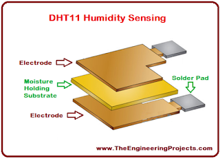
Humidity Sensor: The construction of the humidity sensor includes a moisture-holding substrate that changes its conductivity with the change of the environment. The substrate is placed between two electrodes. The substrate absorbs the water vapor and releases ions. Consequently, the conductance increases which is proportional to the relative humidity. The change in resistance between the electrodes is sensed & processed by the IC and creates the output.

Construction of humidity sensor

Now it leaves no place of questioning, why it's called the capacitive type humidity sensor. This capacitive nature provides accurate measurements regarding humidity. (Dew point, Relative Humidity, Absolute Humidity, etc.)

Temperature Sensor: This is nothing but a thermistor that changes its resistance with the change in temperature. It has a negative temperature coefficient (NTC) which means its resistance decreases with the increment of temperature. 


Sintering refers to the inclusion of semiconductor materials to provide a larger change in resistance with just small changes in temperature.

Pinouts:
The sensor has 4 output pins; Vcc, Data, NC, GND respectively.

Working Principles:
Firstly connect the sensor as per the following diagram and don't forget to add the pullup resistor. (Not required for the sensor module as it has an inbuilt pullup resistor mounted on the PCB)

DHTXX has 8 bit MCU, therefore, it sends data in 8-bit sequences. After sending the starting pulse by the host MCU, DHTXX starts sending data. Both the humidity & temperature data are sent through the data pin in serial transmission line.


Data(40 Bit)= Integer byte of RH; Decimal byte of RH; Integer byte of temperature; Decimal byte of temperature; Checksum/Parity byte

The successful transmission of data is checked by the parity byte. In case of failure, again the data is transmitted.

Parity(8 Bit)= Integer byte of RH +Decimal byte of RH +Integer byte of temperature +Decimal byte of temperature

An example be like,
Data:       00110101  00000000  00011000  00000000  01001101
Parity:     00110101+00000000+00011000+00000000 = 01001101
Decision: Data matched!
Humidity: 00110101 = 35H = 53% RH
Temperature: 00011000 = 18H = 24°C

Accuracy & Specifications:
✦ Temperature Range: 0-50°C with ±2% accuracy
✦ Humidity Range: 20-80% with ±5% accuracy
✦ 3.3 ~5V MCU system.
✦ Operating Current: 0.3~5.5 mA
✦ 16-bit resolution
✦ Long term stability
✦ DHT22 has a more precise, accurate & wider range of working.
✦ 1 Hz sampling rate.


Pitfalls:
This sensor can only provide data that are up to 2 seconds old.

Application Area:
✦ Humidity & temperature measurement
✦ Local weather station
✦ Automatic climate control sensor
✦ Environment monitoring device

Other Sensors:
AM2302, SHT71, TMP100, DS18B20, etc.


Reference Articles:

Image Sources:
* DHgate.com
* Technobyte
* The Engineering Projects
* How to Mechatronics
* Simple-Circuit.com
* ElectronicsHub
* How to Mechatronics


In the late 19th century, something weird happened! A duel was held to establish a commercial dominance. The most surprising fact is that, t...


In the late 19th century, something weird happened! A duel was held to establish a commercial dominance. The most surprising fact is that, though this war took place due to business rivalry, it fixed a standard for the whole world and the present world is witnessing this. Yes, it was the War of Currents that set the standard of AC current all over the world! The war didn't take place all of a sudden. A series of incidents developed the war.

A Little History:
Many of us think that the inventor of DC and AC are Thomas Edison and Nikola Tesla respectively. But it goes without saying that it's not true. Imagine an era when there was no TV, AC, industrial motors, engine, or any advanced technology. At that time the main concern was to enlighten the areas. Previously there were arc lights for large areas or streets and gas lights for the household & business to serve the purpose. But gaslights are not so efficient and arc lamps need high voltage (above 3000V). Some lamps worked well under AC. Several hazards were;

✦ Maintenance is highly complex
✦ Possibilities of fire hazards
✦ Suitable for outdoor lighting
✦ Extremely high voltage was risky to work with
✦ Flickering problem

Carbon Arc Lamp


Edison Illuminating Company:
The famous inventor Edison had a great idea to replace the gas lights with incandescent light invented by him. This brought him great fame as he was able to provide illumination directly into the customer's home with a much lower voltage (nearly 110V). It gained much attention over the US and Edison held several patents and controlled all the key technical developments. By 1882 Edison Illuminating Company (EIC) was established in NY city. The key factors that made DC preferable are, 

✦ DC worked well with incandescent lamp
✦ Incandescent lamp could be powered up using batteries/ storage
✦ Backup power supply was possible
✦ DC worked well with the contemporary motors
✦ Edison specially designed a meter to prepare customer's electric bills that would run only with DC
✦ DC generators can easily be paralleled
✦ DC reduces the high voltage death risks of arc lamps.

Edison with his incandescent lamp


An intelligent entrepreneur!
George Westinghouse, a North American inventor also wanted a share in the electric lighting system. Firstly he went for DC but at that time, AC transformers were growing well in Europe and intelligent Westinghouse understood that instead of becoming a competitor to the well established Edison, it would be better to go for AC. He thought that he can easily operate the AC arc lamps in the streets with high voltage and can support the household incandescent lamp using a step-down transformer. The plus points of AC systems were,

✦ AC can be easily stepped up or stepped down while it is very hard for DC
✦ AC can be transmitted to a large distance but DC can work within a small range around the generator
✦ DC is centralized but AC is not.
✦ DC installations are very costly while AC is quite cheap.

Edison's Yellow Journalism:
Due to different fascinating features of AC,  many other companies like Thomson Houston Electric, United State Illuminating Company, Waterhouse Electric Light Company went for AC development and the generation plants for AC kept increasing. Due to the increasing copper price & popularity of AC became the reason for his loss in low voltage DC supplied by Edison Illuminating Company. From the beginning, Edison opposed AC as he held most of the patents regarding DC. Edison started to spread his negative opinions regarding AC as he had thought that it would be a better option to defame the AC system. Edison, wrote to Edward Johnson, the president of (EIC),
Just as certain as death Westinghouse will kill a customer within six months after he puts in a system of any size. He has got a new thing and it will require a great deal of experimenting to get it working practically 
Even an 84-page pamphlet titled "A warning from the Edison Electric Light Company" was distributed to different newspapers, Edison owned companies & Edison's competitor companies that used AC utilities. The pamphlets mainly focused on the safety of DC and the risks of AC that accidentally caused someone's death.


Reference Articles:


Image Source:
* Honest History
* pixels
* Sutori


Transformation & conversions are other tools that help us to modify our structures. These tools have lessened our complexity in building...


Transformation & conversions are other tools that help us to modify our structures. These tools have lessened our complexity in building geometry. Let us get to know about these operations.

Transformation:
These operations are useful when we need to modify our actual structure. Unlike Boolean or Partitions, we can't merge or split the geometry. 

Array: We can create a rectangular or linear array of the selected geometry by using array transformation. Rectangular array transformation will result in a rectangle while the linear one will extend along with the diagonal. Now you may ask, what will be the range of the array? The extensions are according to the equations below;

 extension (x/y direction) = size (x/y) * displacement (x/y)

Copy: We can copy the selected object and place it on the given coordinates in the displacement box. 
Mirror: This will mirror the object. It requires a point that lies on the point of reflection. Now if we want to draw a line based on a point, numerous straight lines or planes can be formed. So in which direction the object will be mirrored? That's why we need to provide a vector that is normal to the reflection plane/line. Now a few things to be noted;

Increasing X

Y fixed

Reflects to the right

Increasing Y

X fixed

Reflects upwards

Decreasing X

Y fixed

Reflects to the left

Decreasing Y

X fixed

Reflects downwards


Move: We can move the selected object to our desired position. We just need to specify the coordinates.
Rotate: The selected object can be rotated by giving the angle of rotation and the center of rotation. Centre of rotation is the point which will act as the reference while rotation.
Scale: We can increase or decrease the size of the object by giving the scale factor. Scale factor is the ratio to which the size will be updated. The scaling will be conducted taking the center of scaling as the reference. Isotropic scaling will give the same factor for both axes. But anisotropic scaling will give different factors for different axes.

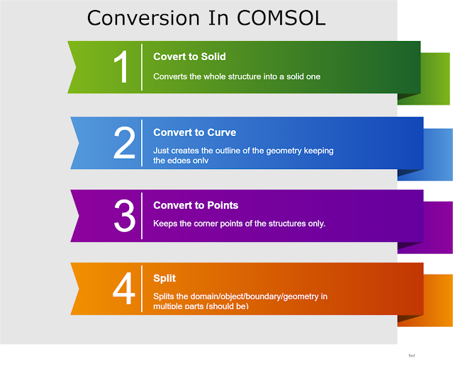
Conversion:
◉ Convert to Solid
◉ Convert to Curve
◉ Convert to Point
◉ Split


◉ Chamfer: Chamfer calls for some vertices and a distance from the vertices. What actually it does, it goes along with every edge associated with the vertice. From the vertice, it calculates the specified distance along with every edge and put points. After that, the points are connected and the rest are discarded from the geometry.
◉ Fillet: It makes the vertices rounded according to the specified radius. Just assume that a rectangle can be transformed into a circle using fillet.


For better visualization, check out the tutorial video here: Transformation & Conversion


Building geometry or structures is very important in COMSOL as the simulation entirely depends on the structure. But there are only a few op...


Building geometry or structures is very important in COMSOL as the simulation entirely depends on the structure. But there are only a few options like circle, square, rectangle, polygon, etc. that COMSOL provides. What to do if our structure is something more than the basic blocks? Here comes the Boolean and Partition operations to modify the structures.

** We will be using 2D models and only the functions will be described. For better understanding please watch the video at the end of the article** 


What is Boolean?
Most of us may know about boolean algebra. It has only two variables; True/False, 0/1, Yes/No, etc. We can apply the same operations in case of structures. But eventually, you will find that, instead of Boolean, they more relate to Set operations. In COMSOL, the operations are named as;

 Union: This operation is like 'addition' process. We can turn multiple different domains into a single one using a union. Here, if we wish, we can leave the intersected boundary edges as it was or we can remove the edges.
◉ Intersection: We can keep the intercepted area of the domains by this operation.
◉ Difference: It is the 'subtraction' operation. It gives two selection window. One is for the domains to be added and the other is for the subtracted domains. The subtracted domains along with the intercepted portions with the added domains will disappear from the structure.
◉ Composition: Now composition allows us to make customized geometry. We just need to select the domains and make an equation, a boolean equation, that serves our purpose. 


Partition:
Partition basically tends to make parts inside the domains or objects. Now parts can be created inside the object body or on the edges.

Object Body: To make the parts inside the body, we either need another object to specify the part or some lines to separate the parts. To create parts with the help of another object, we need to go for the 'partitions objects' option and select the object to partition and the tool object.
Again if we want to partition the domains, we need to choose some vertices that will draw some lines and will create the partitions. For this, we need to choose the 'partition domains' and select the necessary parameters.
Edge Partition: This will part the selected edges according to the given ration. We just need to choose the edges here and fix the ration. This will create two separate partitioned edges from a single one.

Check out the video below to have better visualization: Boolean operations & Partitions


Image Source:
* COMSOL Multiphysics
* Stack Overflow


Till now we've discussed the pre-requisites to build structures in COMSOL. Today we will explore some of the base structures like circle...


Till now we've discussed the pre-requisites to build structures in COMSOL. Today we will explore some of the base structures like circle, rectangle, square, polygon, etc. This will lead us to build complex models in the future. 

Geometry Console:
Right-click on the geometry node and you will find 10 structures as;
* Circle
* Ellipse
* Rectangle
* Square
* Polygon
* Point
* Parametric Curve
* Line Segment
* Interpolation Curve
* Bezier Polygon

To build the specific structure, you just need to select the structure and the related settings will be available in the Settings window.

Geometry Settings:
No matter what geometry you choose, there'll be mostly similar segments in the settings window.


The flowchart briefly explains the functions of the geometry settings. But for some structures, there are some more options available. Let us talk about them separately.

Special Fields:
Sector Angle (Circle): One can modify the share of the circle by inserting the angle value here. For example, 360° for a full circle, 180° for half circle, 90° for quarter circle, etc.
Coordinates (Polygon): Takes the coordinates of the polygon.


Expression (Parametric Curve): As the name suggests, parameter refers to another variable (let 's') rather than actual variables (let x,y) in a problem. And the actual variables are expressed through that parameter by some equations. Therefore 's' requires a minimum and maximum value and the expressions for the actual variable. For example,

x= 0.5*s+2*s^2  and
y= 5*s-3*s^2 where  -1≤ s ≤1


Start & End Point (Line Segment): It calls for the selection of the start and endpoint of the line. One can manually enter the coordinates of the line by choosing coordinates in the specify dialogue box.
Data Source (Interpolation Curve): Similarly like the coordinates in Polygon, the same options are provided here for data entry (Vector, File, Table). One just needs to specify the data here.


Don't forget to watch the video on building project in COMSOL: Geometry in COMSOL Multiphysics


Learning new things is always interesting. The inborn thirst for learning new and new concepts differentiates human beings from other creatu...


Learning new things is always interesting. The inborn thirst for learning new and new concepts differentiates human beings from other creatures. The Almighty has blessed us with this virtue. But the eagerness for knowledge can also derail us from our actual motives. ''Is this guy out of his mind!''- you might be thinking this about me. But yes, it's true. I'm talking about the Learning Loop.


What Is Learning Loop?
The learning loop is a tool that helps you to define how the work you do now informs     what you do next. It provides a high level perspective on how implementing social change   can be broken down into a gradual process of iterative cycles
In simple language, a learning loop helps you to build a sequential structure that helps you to learn in a better & quicker way. You can have a single, double, or multiple loop for your purpose.

Examples of some learning loops 


How Easy Is Learning?
Learning loop can be extremely helpful for a strategic process if and only if you can stick to your purpose. Now, what does it mean? Being an engineer you have lots of interesting topics to learn. You can go for programming languages like C/C++, Python, Java or you can learn HTML, CSS, JS. Even if you are a tech-enthusiast, you may become passionate to learn Robotics, Machine Learning, Image Processing & MATLAB. Again you can be a beginner who wants to learn Arduino or Raspberry Pi. There are numerous fascinating things out there. You just have to type and learn. 

Actually, you are lucky enough to have institutions like Coursera, Udemy, Youtube where you can learn the things from the finest teachers and instructors from all over the world. A few years earlier it was a fantasy and people need to struggle hard for learning.

Is It Wrong to Learn?
Have you ever read a research paper? You don't need to be a researcher to read a paper. Just go to Google Scholar and search for any topic you find interesting. When you go through the paper, you will find several new terms. For example, if you try to read a paper on an Arduino project, you might find terms like TTL, Ram, Sram, Flash Memory, ATmega, etc. Now let us try to relate the things,

Action: Reading a paper
Reader's Status: Beginner
Objective: To know the structure of a paper
Field of Interest: Arduino
Growing Interest: TTL, PCB, ATmega, IDE, Open Source, etc.
Result: Arduino projects

As you can see, in this hypothetical case, a beginner who is interested to know about the structure of a research paper ends in Arduino projects. While you keep searching the ins and outs of Arduino and the relative terms to "understand" the paper, you have deviated from your prime motive which was the structure of the paper. So we can say you are stuck in a learning loop.

Therefore there is no harm in learning but one should keep stick to his motive. Otherwise while searching for one term, you will get several more unknown terms and this loop will go on.


How to Get Rid of the Loop?
A curious mind is always eager to learn. But being a part of a loop will neither satisfy your objective nor help you in learning. Basically, beginners are the prey to this. One should adopt the following steps to avoid the loop;

✔ Fix the specific topic
✔ Set the objectives
✔ Make a sequence tree to achieve the goals
✔ Note down the new terms
✔ Divide them into different categories according to their applications
✔ Filter the relevant terms to your specific topics
✔ Get to learn!


Get to know more about the learning loop from the video here; How to learn way faster using learning loops


Image Source:
* SlideShare
* Medium
* Learn Forward AB
* Dr. Helen Barett
* 123RF.com